Sunday, September 27, 2015

ATtiny85 and Adafruit NeoPixel

If you decide to program an ATtiny85 to control Adafruit NeoPixel, it may be necessary to reset chip fuse to 8 Mhz.
I bought ATtiny85-20PU  from mouser.com. This chip has an internal clock and can do 1 Mhz and 8 Mhz.
I believed it is shipped set to 1 Mhz, which will not work with the Adafruit NeoPixel.

Here are a few reminders.


  • Download Arduino 1.6 or greater
  • Installing the ATiny85 configurations in the Arduino IDE
    • Click File -> Preferences and enter the following url in field Additional Boards Manager Urls
      • https://raw.githubusercontent.com/damellis/attiny/ide-1.6.x-boards-manager/package_damellis_attiny_index.json
  • I am using an Arduino Uno to program the ATtiny85, configured as follow
    • If you are using a programmer to upload the code to the ATitny85, you still need to reset the fuse once.

  • Load the sketch -> Examples -> ArduinoISP
    • Compile
    • Upload into the Arduino Uno
  • Load the Exemples -> 01.Basics -> Blimk
  • In the menu tool select
    • Board: ATtiny
    • Processor: Attiny85
    • Clock: 8 Mhz (Internal) 
    • Port: Com port used by the Arduino
    • Programmer: Arduino As ISP
  • Fuses
    • This is the tricky part. It is necessary to reset the clock of the chip.
      It is a one time operation.
      From the menu Tool, click Burn Bootloader
  • Now you can upload the code from NeoPixel Code from Adafruit.It should work.

    Thursday, September 10, 2015

    I2C protocol visualization with Nusbio

    I wanted to show you this breadboard experiment, inspired by the Arduino on board led
    and also the blogpost Arduino from scratch part 6 – pin 13 led by Rheingoldheavy.com


    2 weeks ago I was trying to connect LEDs to each nusbio gpio in parallel to create an on board led feature. And it does not work well and there are side effects, like i2c stop working completely.

    So I gave up. But then I heard about the blog post and I just try with an lm358 op-amp and it is working.

    Now I am can create my 8 blue on board LEDs PCB. Each LED will light up when the associated gpio is on. It also work when the gpio is open as input in pull up mode.
    obviously I will need 8 op-amp.

    In the future I will add the 8 blue LEDs and op-amps directly on Nusbio board.
    That was one of my idea since day 1.

    In this video I plugged an Adafruit i2c 8x8 led matrix into my device Nusbio.
    Gpio 0 for the clock and gpio 1 for the data.

    I connnected the blue led to gpio 0 via one op-amp and gpio 1 to the red led via the other op-amp (an lm358 is dual op-amp).

    I also reduce the speed of the clock to lowest i could which is 1200 baud.


    In this video we see the blue and red led flickering. what does it mean?

    Well when the blue led is on (the clock) and the red led (the data) is on we are transmetting a 1 from the master to the slave or from the salve to the master and when the red is off we are transmitting a 0.

    The red led flickering is the 1 and 0 being sent across the wire. The blue led is the clock, so it just go on/off, on/off  is barely visible.

    I thought it was cool way to visualized what is going on on an i2c bus, though it is not very precised.

    Thanks.

    Wednesday, September 9, 2015

    Controlling RGB LED Strip with VB.NET

    Nusbio extension samples are now available in VB.NET.

    Finishing the code for  RGB LED Strip extension in VB.NET.


    Github:

    Controlling bi color led with vb.net. Yes you can.

    Nusbio extension samples are now available in VB.NET.

    Finishing the code for the Bi-Color LED extension in VB.NET.

    Github:


    Saturday, August 8, 2015

    Transistor as a switch reminder

    This is an image from blog post "Using Transistor as a Switch" from ermicro.com blog,
    which is really clear, may be a little bit too long and too in depth.

    As a reminder specially for NPN transasistor I am refrerencing the blog post and schematic.


    Friday, July 24, 2015

    Blinking one LED or two from a Windows machine.

    One simple way to blink one LED from a Windows machine.
    No code involved.
    Video.


    Eagle Cad File on github: OneLedBlinker


    Thursday, June 25, 2015

    GDevice is now renamed Nusbio

    On June 23 2015, I renamed the device from GDevice to Nusbio.

    This will explain why on previous post the device referenced as GDevice.

    How fast can I turn a Nusbio gpio on and off in C#

    How fast can I turn a Nusbio gpio on and off in C#?

    The oscilloscope says 1 Milli second to turn it on, 1 Milli second to turn it off.


    How fast can I turn a extra gpio pin on and off in C#?

    The extension Ex8G32kE, add an extra 8 gpio pins and a 32k EEPROM to Nusbio.

    For the extra gpio pins, I used the MCP23008 gpio expander. The MCP23008 is an I2C device.


    To turn on the extra gpio pin, the method DigitalWrite() in the C# class MCP23008, makes 2 I2C calls (GetGPIOMask() and SetGPIOMask()) to turn on the gpio.


    public override void DigitalWrite(byte gpioIndex, MadeInTheUSB.GPIO.PinState d)
    {
        var mcpIndex = gpioIndex - this.GpioStartIndex;
    
        // only 8 bits!
        if (mcpIndex > 7) return;
    
        // read the current GPIO output latches
        int gpio = GetGPIOMask();
    
        // set the pin and direction
        if (d == GPIO.PinState.High)
        {
            gpio |= (byte)(1 << mcpIndex);
        }
        else
        {
            gpio &= (byte)(~(1 << mcpIndex));
        }
        // write the new GPIO
        SetGPIOMask((byte)gpio);
    }
    
    internal int GetGPIOMask()
    {
        // read the current status of the GPIO pins
        return this._i2c.Ready1Byte8BitsCommand(MCP230XX_GPIO); 
    }
    
    internal bool SetGPIOMask(byte gpio)
    {
        return this._i2c.Send2BytesCommand(MCP230XX_GPIO, gpio);
    } 
     
    How fast can I turn a extra gpio pin on and off in C#?
    The oscilloscope says 7.4 milli second to turn it on, 7.4 Milli second to turn it off. 
    We can estimate the cost of one I2C call to 3.7 Milli second.


    Source Code

    Thursday, June 18, 2015

    Nusbio 8 Button Panel


    All I wanted to do was to create an 8 keys keyboard PCB, but I wanted to light up one LED if at least one key was pressed. This will be the GDevice extension kit, 8 Buttons Panel.


    Just Buttons


    First, the basic schematic for 2 buttons, with no LED.


    This is generally how I handle buttons, using what is called a Pull Down resitor.
    1. The current start flowing from VCC (pin 9) and arrive as the input of the buttons (Switch) S0 and S1. 
    2. When the button S0 is pressed the current flow through the button and goes to ground via the resistor rp0 and also goto to the gpio 0 (pin 1). When the button S2 is pressed the following method gDevice.GPIOS[GDeviceGpio.Gpio0].DigitalRead(), returns High. When the button  is not pressed the method returns Low.
    3. Button S1 works the same and could be the same for another 6 buttons, for a total of 8 buttons.
      Since the GDevice offers 8 gpios.

     With a LED.


    Now I want to add an LED that will light up if at least one button is pressed.


     This was my first thought, and luckily I tested this on a bread board, because there is an issue
    • When the button S0 is pressed the current flow 
      • To ground via the resistor rp0
      • To Gpio0
      • To the led LEDKBD and to ground via resistor RLEDKBD. The resistor light up.
    So far so good.

    When the button S0 is pressed the method,
    gDevice.GPIOS[GDeviceGpio.Gpio0].DigitalRead() returns High, but the method
    gDevice.GPIOS[GDeviceGpio.Gpio1].DigitalRead() also return High.

    What?

    Yes, now that the current flow into the LED LEDKBD from the button S0, it also flow using the other branch that lead to Gpio1, providing 5 volt to Gpio1.  And therefore that means S1 is pressed.
    Well no, it means there is an issue with the circuit.
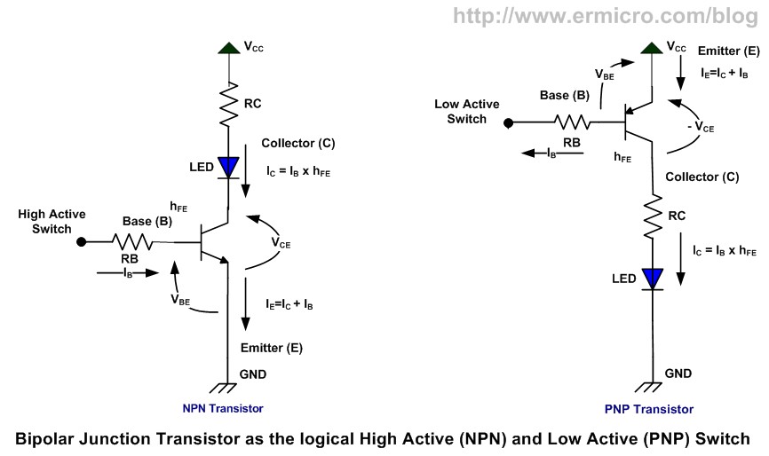
    Diode


    Since I want to prevent the current to flow back from button 0 to Gpio 1 when button 0 is pressed, or
    from button 1 to Gpio 0 when button 1 is pressed, I thought diode (A diode allows the current to go to only one direction).


    The good thing, it is working. but now for my 8 Buttons Panel kit, I have 8 buttons, 8 resistors and 8 diodes. This raise the following issues:
    • Difficulty of the kit increase
    • Price of the kit increase, PCB real state and diode have a cost.
    Is there a simpler way?

    That is why I go to the Artisans Asylum hacker space, on wednesday. So I can ask for help.
    So here is the answer.

    If one or more button are pressed the current flow from VCC to GND and therefore the LED will light up. The previous solution with the diodes may be considered a better one, because in this last solution the LED being first create a voltage drop, and the voltage that goes into the Gpios is 1.8 volt rather than 5 volt, this could not be considered as a true High. But with the GDevice it is working.

    About the resistors. For a Pull Down resistor 10 k is the more conventional. But in this case this will also affect the brightness of the LED. So 1 or 2 k is probably what I will chose.


    Final Schematic


    Few months ago I discovered resistor array. For example the 652-4610X-1LF-1K, is 9 x 1k resistors.
    and the advantage is that it offer 9 input, 9 1k resistors but only one output, that in my case will go to ground.

    This is not for all solution, but if all the output of the resistors go to the same wire, this save n-1 wire and soldering and space in the PCB. You can find resistor array in different grouping : 4, 8 , 9, 13.
    You can also find resistor array with  n input and n output.

    But here my final schematic for the Nusbio 8 Buttons Panel PCB.


    The LED LEDPWR, is just here to show that the extension is correctly connected to the GDevice.
    I also added a jumper, so I can easy, plug a multi meter and measure the current.

    Thursday, May 28, 2015

    MCP23008 8 gpio extender for Nusbio

    Overview 

    I just implemented a C# class to plug a 8 gpio extender named

    This chip is an I2C chip therefore I need to use 2 of the Nusbio gpio (gpio0: clock, gpio1: data) to control it, but in exchange I get an extra 8 gpios.

    8 - 2 + 8 = 14 GPIOs

    It is possible to add more than one MCP23008 on the same bus.

    I2C vs SPI

    Becarefull MCP23S08 is the SPI version and for now, you need the I2C one which is MCP23008.
    SPI support for the Nusbio will come in the next few weeks.

    More GPIO


    The chip MCP23017 is an 16 gpio extended part of the same familly. I will add support for it in the next few weeks. In some way the MCP23017 is superior because
    • It had twice more GPIO
    • 15% more expensive
    • Similar wiring
    • But it takes more space on the board


    Saturday, May 16, 2015

    MCP4725 12 bits digital to analog converter (DAC) controled from C#

    Today I tried the MCP4725 12 bits digital to analog converter (DAC) using the Visual Studio, C# and the GDevice.

    The MCP4725 is an I2C device and it worked like a charm with the I2C class.

    I am using the Adafruit breakout.  The Sparkfun breakout should work, any breakout  should work.
    On the breakout the 2 pull up resistor are already there.


    Friday, May 15, 2015

    Adafruit Small 1.2" 8x8 LED Matrix + Backpack controlled with a GDevice in C# from Visual Studio


    The GDevice supports the I2C protocol and therefore allows me to control 2 Adafruit Small 1.2" 8x8  LED Matrix + Backpack or more.

    Both LED matrix are on the same I2C bus.

    I am using a C# from Visual Studio.


    Tuesday, May 12, 2015

    A picture of 2 Adafruit Small 1.2" 8x8 Bright Square Pure Green LED Matrix + Backpack, on the same i2c bus controlled by a GDevice program written in C#.

    It is working. Next step getting an EEPROM to work on the same bus with the 2 LED matrix.


    Tuesday, May 5, 2015

    PWM api for the GDevice

    I am working on the PWM API for the GDevice library.
    Internally the api pre compute a buffer and send the buffer to the FT232RL, which will modulate using its own clock. Therefore it can be called hardware PWM.

    The method is blocking the C# execution, but does not use any CPU.


    In this sample I setup the speed to 8k baud, my buffer size is 16k.
    It is kind working, though when applied to an LED I see some unexpected flickering


    I still have to work on these parameters, but here is a first Video.
     
    Follow Up:
    After looking into it with an oscilloscope, well the modulation is completely wrong.
    I guess more research on the way.


    Saturday, May 2, 2015

    GDevice1.0 Last Prototype Tour

    I am getting close to have a first final design, my first PCB was not a complete success, but I found my enclosure. And may 3D print the front and back panel. I ordered 

    Here is a video of the last prototype

    Video.

    GDevice LED Panel

    Here is the first panel or shield I designed for the GDevice, it is my second PCB and I got it right.


    The video.

    Monday, March 23, 2015

    Introducing the GDevices Prototypes (GPIOs for Windows)

    GDevice1 (Previously LDevice1)

    The GDevice1 is an  USB device that offers 3 LEDs (Red, Yellow and Green), one switch and 4 GPIOs (General Purpose Input Output) to Windows, programmable with any .NET languages.


    GLDevice2 

    The GDevice2 is an  USB device that offers 8 GPIOs (General Purpose Input Output) to Windows programmable with any .NET languages.


    Videos