Sunday, September 27, 2015

ATtiny85 and Adafruit NeoPixel

If you decide to program an ATtiny85 to control Adafruit NeoPixel, it may be necessary to reset chip fuse to 8 Mhz.
I bought ATtiny85-20PU  from mouser.com. This chip has an internal clock and can do 1 Mhz and 8 Mhz.
I believed it is shipped set to 1 Mhz, which will not work with the Adafruit NeoPixel.

Here are a few reminders.


  • Download Arduino 1.6 or greater
  • Installing the ATiny85 configurations in the Arduino IDE
    • Click File -> Preferences and enter the following url in field Additional Boards Manager Urls
      • https://raw.githubusercontent.com/damellis/attiny/ide-1.6.x-boards-manager/package_damellis_attiny_index.json
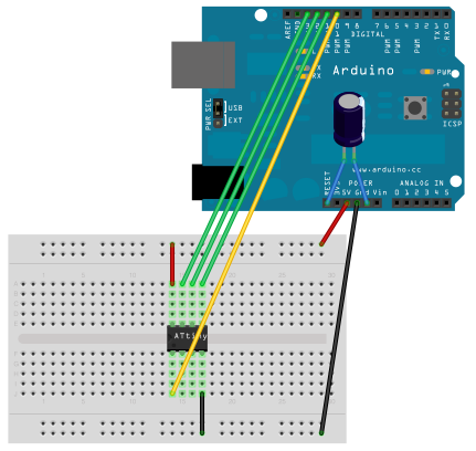
  • I am using an Arduino Uno to program the ATtiny85, configured as follow
    • If you are using a programmer to upload the code to the ATitny85, you still need to reset the fuse once.

  • Load the sketch -> Examples -> ArduinoISP
    • Compile
    • Upload into the Arduino Uno
  • Load the Exemples -> 01.Basics -> Blimk
  • In the menu tool select
    • Board: ATtiny
    • Processor: Attiny85
    • Clock: 8 Mhz (Internal) 
    • Port: Com port used by the Arduino
    • Programmer: Arduino As ISP
  • Fuses
    • This is the tricky part. It is necessary to reset the clock of the chip.
      It is a one time operation.
      From the menu Tool, click Burn Bootloader
  • Now you can upload the code from NeoPixel Code from Adafruit.It should work.

    Thursday, September 10, 2015

    I2C protocol visualization with Nusbio

    I wanted to show you this breadboard experiment, inspired by the Arduino on board led
    and also the blogpost Arduino from scratch part 6 – pin 13 led by Rheingoldheavy.com


    2 weeks ago I was trying to connect LEDs to each nusbio gpio in parallel to create an on board led feature. And it does not work well and there are side effects, like i2c stop working completely.

    So I gave up. But then I heard about the blog post and I just try with an lm358 op-amp and it is working.

    Now I am can create my 8 blue on board LEDs PCB. Each LED will light up when the associated gpio is on. It also work when the gpio is open as input in pull up mode.
    obviously I will need 8 op-amp.

    In the future I will add the 8 blue LEDs and op-amps directly on Nusbio board.
    That was one of my idea since day 1.

    In this video I plugged an Adafruit i2c 8x8 led matrix into my device Nusbio.
    Gpio 0 for the clock and gpio 1 for the data.

    I connnected the blue led to gpio 0 via one op-amp and gpio 1 to the red led via the other op-amp (an lm358 is dual op-amp).

    I also reduce the speed of the clock to lowest i could which is 1200 baud.


    In this video we see the blue and red led flickering. what does it mean?

    Well when the blue led is on (the clock) and the red led (the data) is on we are transmetting a 1 from the master to the slave or from the salve to the master and when the red is off we are transmitting a 0.

    The red led flickering is the 1 and 0 being sent across the wire. The blue led is the clock, so it just go on/off, on/off  is barely visible.

    I thought it was cool way to visualized what is going on on an i2c bus, though it is not very precised.

    Thanks.

    Wednesday, September 9, 2015

    Controlling RGB LED Strip with VB.NET

    Nusbio extension samples are now available in VB.NET.

    Finishing the code for  RGB LED Strip extension in VB.NET.


    Github:

    Controlling bi color led with vb.net. Yes you can.

    Nusbio extension samples are now available in VB.NET.

    Finishing the code for the Bi-Color LED extension in VB.NET.

    Github: